
1. Product Definition and Application Scope
The high pressure liquid cooling hose with 2.5MPa (approximately 360psi) working pressure rating is a wire braid reinforced flexible tube engineered for circulating cooling water in industrial thermal management systems. This product category addresses the growing demand for reliable, high-performance fluid conveyance in applications where conventional rubber or thermoplastic hoses would be inadequate due to pressure requirements, temperature extremes, or mechanical stress conditions.
Industrial water cooling systems represent a critical infrastructure component across multiple sectors. In manufacturing facilities, cooling water circulates through welding equipment, induction heating systems, injection molding machinery, and laser cutting apparatus. In power generation, cooling water removes heat from transformers, generators, and auxiliary equipment. In data centers, water-cooled systems are increasingly deployed to manage the thermal loads of high-density computing equipment. In process industries, cooling water supports chemical reactors, distillation columns, and heat exchangers.
The 2.5MPa working pressure rating provides capacity for systems operating at elevated pressures typical of closed-loop cooling circuits, including those with significant elevation changes, long piping runs, or pumps sized to overcome system pressure drops. The wire braid reinforcement ensures the hose maintains dimensional stability under pressure while providing the burst safety margin necessary for industrial applications.
2. Technical Specifications and Performance Parameters
Pressure Ratings: The 2.5MPa working pressure rating defines the maximum continuous operating pressure that the hose can sustain under normal service conditions. Proof test pressure is typically 1.5 times the working pressure, reaching 3.75MPa. Minimum burst pressure, reflecting the ultimate structural capacity of the hose, is specified at four times the working pressure, or 10MPa. This 4:1 safety factor provides a substantial margin against pressure surges, water hammer events, or system malfunctions that could temporarily elevate system pressure.
Temperature Range: The hose is engineered for reliable performance across a broad temperature spectrum. Standard industrial water cooling applications range from -40°C to +100°C, accommodating cold ambient conditions in outdoor installations and elevated temperatures from process equipment. Specialized versions may extend the upper limit to +120°C or +150°C for high-temperature cooling or warm water recirculation systems.
Inside Diameter and Flow Capacity: Available inside diameters typically range from 6mm to 50mm, with standard sizes including 10mm, 13mm, 19mm, 25mm, and 32mm. The flow capacity is determined by the inside diameter and the system operating pressure. For industrial water cooling applications, flow velocities typically range from 1.5 to 3.0 meters per second, providing adequate heat transfer while limiting pressure drop and erosion potential.
Bend Radius: The minimum bend radius is influenced by both hose diameter and reinforcement construction. For wire braid reinforced hoses, typical bend radii range from 3 to 6 times the hose outside diameter. This bend radius capability allows routing through industrial equipment enclosures with moderate space constraints.
Vacuum Resistance: The wire braid reinforcement provides structural support that prevents collapse under negative pressure. The hose can typically withstand full vacuum (approximately -0.1MPa) without deformation or flow restriction, a critical attribute for suction-side applications in pumping systems.
3. Material and Construction Architecture
Inner Tube: The fluid barrier layer is manufactured from a material selected for compatibility with water and water-glycol coolant mixtures. Common materials include EPDM (ethylene propylene diene monomer) rubber for applications requiring resistance to glycol additives, and NBR (nitrile butadiene rubber) for applications involving oil-contaminated water or coolant formulations containing petroleum additives. The inner tube is extruded to a smooth internal surface that minimizes flow resistance and reduces biofilm formation in industrial water systems. The material formulation includes antioxidants and anti-degradants to extend service life in high-temperature water environments.
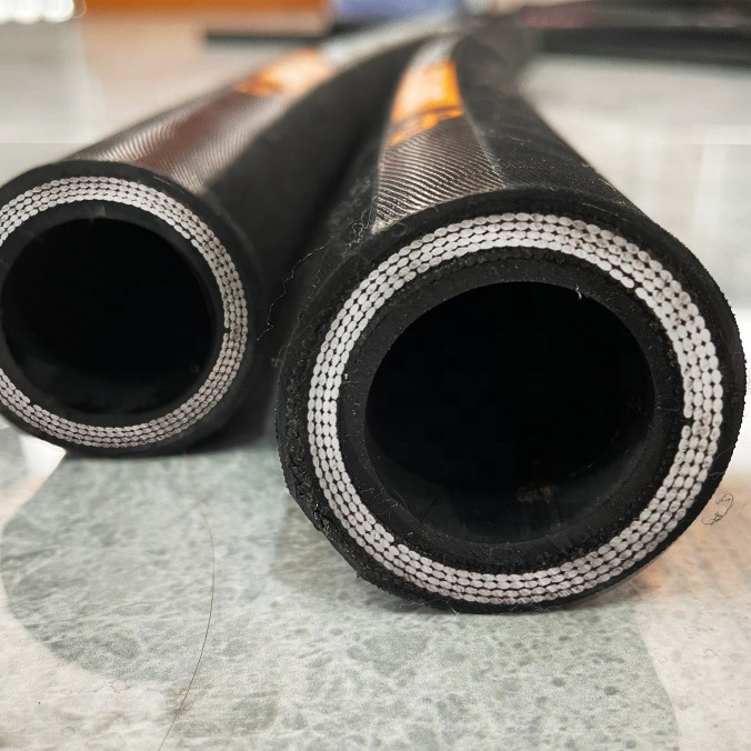
Wire Braid Reinforcement: The reinforcement structure consists of one or more layers of high-tensile steel wire braid applied over the inner tube. The wire braid is constructed using multiple wire ends interwoven at a controlled braid angle, typically between 54° and 58° relative to the hose axis, to balance pressure containment and flexibility. The wire material is typically high-carbon steel with tensile strength exceeding 2000MPa, drawn to specified diameters and coated with a bonding agent to ensure adhesion to the surrounding rubber layers. The braid coverage is typically 80% to 95%, with higher coverage providing greater pressure capacity and burst resistance.
Outer Cover: The exterior layer is formulated from abrasion-resistant and weather-resistant rubber compounds. For industrial water cooling applications, the cover must resist ozone cracking, ultraviolet degradation, and mechanical abrasion from contact with equipment structures. Common cover materials include neoprene (polychloroprene) or chlorinated polyethylene compounds. The cover thickness is selected to provide adequate protection while maintaining the overall flexibility of the hose assembly.
Layer Bonding: The inner tube, braid reinforcement, and outer cover are bonded through the vulcanization process. The wire braid may be treated with an adhesive or rubber cement to promote adhesion to the adjacent rubber layers. The bonding integrity is verified through adhesion testing as part of the quality control program.
4. Wire Braid Reinforcement Engineering
Pressure Capacity Determination: The wire braid reinforcement is the primary structure for containing internal pressure in the 2.5MPa working pressure hose. The pressure rating is determined by the wire tensile strength, the number of wire ends in the braid, the braid angle, and the coverage percentage. Engineering calculations using the thin-wall pressure vessel theory, modified for braid geometry, establish the relationship between burst pressure and construction parameters.
Braid Angle Optimization: The braid angle is selected to balance pressure containment and flexibility. At the design equilibrium angle of approximately 54°44‘, the braid maintains constant length and diameter under pressure. Deviations from this angle result in length change or diameter growth under pressure, which may affect end fitting performance and system compatibility.
Fatigue Resistance: Wire braid reinforced hoses are subject to fatigue from pressure cycling and flexing during operation. The wire material and braid construction must withstand the specified number of pressure cycles without failure. Fatigue testing is performed on production samples to verify the design meets service life expectations.
5. Industrial Water Cooling Applications
Welding Equipment Cooling: Automated welding systems employ water cooling to remove heat from welding torches, power cables, and transformer rectifiers. The 2.5MPa working pressure rating accommodates the pump pressures typical of these systems. The hose flexibility enables routing around robotic arms and moving equipment.
Induction Heating Systems: Induction heating power supplies and work coils require water cooling to maintain performance and prevent component damage. The cooling water circulates through the induction coils, where the hose must withstand elevated temperatures and possible exposure to magnetic fields.
Injection Molding Machine Cooling: Injection molding machines use water cooling to control barrel and mold temperatures. Multiple cooling circuits may be present, with hoses routing water between the machine and the central cooling system. The hose must resist oil contamination and abrasion in the factory environment.
Data Center Liquid Cooling: Water cooling in data centers employs liquid cooling systems to remove heat from server racks. The hoses distribute cooling water to the cold plates or rear-door heat exchangers located within the racks. The wire braid reinforcement provides the pressure capacity required for the cooling distribution system.
Laser Cutting and Welding Systems: High-power lasers generate significant heat requiring efficient cooling. The hose transports water to the laser head and associated optics cooling circuits.
6. Installation Practice and System Integration
Routing and Support: The hose should be routed with adequate clearance from moving equipment, sharp edges, and heat sources. Support brackets or clamps should be used at appropriate intervals to prevent sagging and vibration. The bend radius must be maintained above the specified minimum, particularly near end fittings where stress concentration is highest.
End Fitting Attachment: The hose ends are fitted with connectors suitable for industrial water cooling systems. Common fitting types include barbed fittings with hose clamps, compression fittings, quick-disconnect couplings, and threaded connectors. Swaged or crimped fittings are typically used for higher pressure and critical applications to ensure pull-out resistance.
System Flushing: Before installation, the cooling system should be flushed to remove debris that could become lodged in the hose or fittings. The hose should be connected only to clean fluid sources to prevent contamination from entering the cooling circuit.
Pressure Testing: After installation, the complete cooling circuit is pressure tested to verify system integrity. The test pressure should be at least the system working pressure, and leak checks should be performed at all connection points.
Online Message
Please fill in your name and message, and don't forget to email and/or call if you wish. We will reply within 24 hours.
